
Usage
Prerequisites
Completed ROSie installer and workspace setup.
Generating ROS 2 - PLC Connection
1. Create interface description file config.yaml
At first a YAML file has to be created, which specifies the interfaces between ROS 2 and the used PLC program according to the rules described in the YAML Configuration Structure. This YAML file should be saved into the input folder in your ROSie Workspace.
A template for a working configuration looks like this:
# System description of the generated PLC code and ROS 2 package
system:
  ros2:
    package_name: rosie_example_package # Generated ROS 2 package name
    node_name: rosie_node # Generated ROS 2 node name
  rib:
    RIB_App_IPv4: 127.0.0.1 # IPv4 address of the SHM control app: RIB_App
    RIB_App_port: 27567 # Port of the SHM control app: RIB_App
    RIB_Version: "v2.2.4" # Installed RIB version [v2.1.1, v2.2.4]

# All topics that subscribe to a ROS 2 topic and write its data to the PLC
ros2_to_plc:
  topics:
    - type: "geometry_msgs/msg/Twist.msg" # The full ROS 2 message type defintion
      ros2_topic: "/cmd_vel" # The ROS 2 topic name, also acts as DataBlock identifier in the PLC
      rate: 200.0 # in [Hz]

# All topics that read data from the PLC and publish it on a ROS 2 topic
plc_to_ros2:
  topics:
    - type: "sensor_msgs/msg/BatteryState.msg" # The full ROS 2 message type defintion
      ros2_topic: "/battery_state" # The ROS 2 topic name, also acts as DataBlock identifier in the PLC
      rate: 10.0 # in [Hz]
Please note that there is also a provided example file under
workspace/input/valid_config_example.yaml
2. Start ROSie container
If you completed the ROSie setup successfully, you can now start the ROSie container by running the following command in the terminal:
start-rosie
Optional: Manual setup of the ROSie environment and start of the container
In case the install script was not executed, the ROSie environment can also be set up manually. Navigate to the installed ROSie package:cd path/to/rosie_workspace
# [REQUIRED]
# The users ROS 2 base installation path share directory that contains all standard interfaces including their .msg files.
# This directory has to be be mounted in the ROSie container to be able to lookup all standard types.
# Standard ROS 2 installation example: /opt/ros/jazzy
# Custom ROS 2 installation example:   /home/user/jazzy_ws
USER_ROS2_INSTALLATION_PATH=/opt/ros/jazzy

# [OPTIONAL]
# The user directory where the optionally needed custom ROS 2 interfaces are installed
# Example: /home/user/ros2_ws
# ros2_ws
#     |-- build
#     |-- install
#     |-- log
#     |-- src
#         |-- custom_msgs
USER_ROS2_INTERFACE_INSTALLATION_PATH=/home/user/ros2_ws

# [REQUIRED]
# The current directory where this .env file and the whole provided ROSie workspace is located
USER_ROSIE_WORKSPACE_PATH=/home/user/rosie_workspace
docker compose run --name ROSie --rm ROSie
3. Generate PLC code using the ROSie command line tool
In the container environment, start the generation of the PLC code by choosing a configuration .yaml file located within the Workspace input folder.
rosie -c <config_file_name>.yaml
If your configuration is valid the output should look similar to this:
$ rosie -c config.yaml
#####################################  ROSie  #####################################
#  Version: 0.3.0                                                                 #
#  Date:    08.07.2025                                                            #
#  Time:    14:21:38                                                              #
#  Copyright (c) Siemens AG, 2025, and licensors. All rights reserved.            #
#  Portions include Open Source Software. See ReadMe_OSS_0.3.0.html for details.  #
###################################################################################

Gathering ROS 2 message types information ...
Generating PLC code ...
Please import the generated PLC code into your TIA project, export the TIA project .psc file, and place into the ROSie input folder.
Please provide the file name of the .psc in the prompt when requested, e.g., 'tia_project.psc' and press ENTER to continue the generation process or 'n' and ENTER to exit the program.
Inside the output folder of your ROSie workspace a time-stamped folder has been created, that contains the generated PLC code. The path to the generated PLC sources is similar to the following:
workspace/output/time-stamp/output/plc_code/<time-stamp>_rosie_generated_rib_scl_structs.scl
4. Move generated PLC code to TIA V20 engineering machine
Now move the generated PLC source file <time-stamp>_rosie_generated_rib_scl_structs.scl to your TIA engineering machine. If you use a virtual machine you can use shared folders for example.
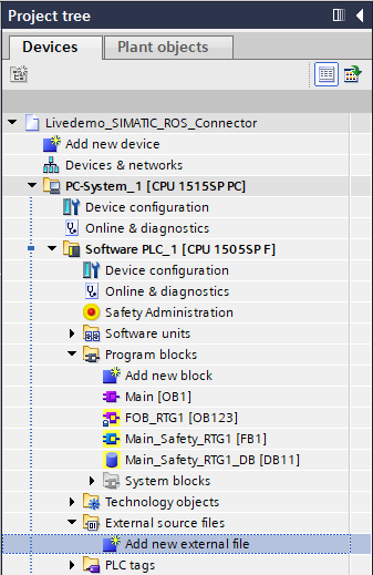
5. Import generated PLC source as external source file
Open the TIA project of your IPC or OpenController that shall establish a connection to ROS 2. Select the Software-Controller of the device and import the previously generated PLC source file into your TIA V20 project.
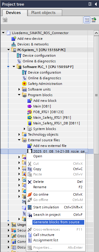
6. Generate blocks from external PLC source file
The imported source file can now be used to generate the PLC program blocks of the ROS 2 <-> PLC connection:
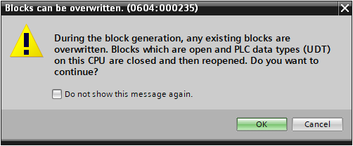
There will be a warning message informing you that any duplicate blocks will be overwritten. Make sure to have a backup of your project and acknowledge the warning dialog.
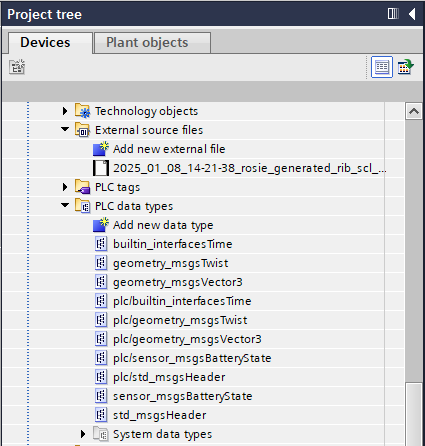
Afterwards the following blocks are generated into your TIA project:
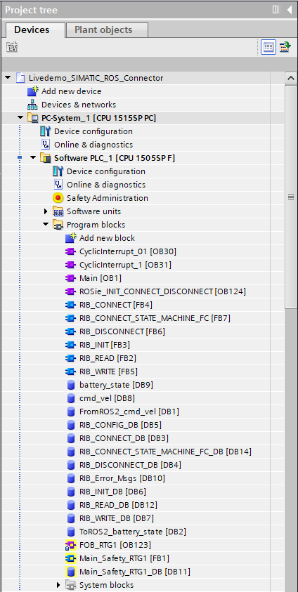
And the following UDTs representing the ROS 2 msg types inside your TIA portal:
7. Create .psc file of the device containing the ROSie generated blocks
To proceed with the generation of the ROS 2 package of the ROS 2 <-> PLC connection a .psc file has to be created from your device inside the TIA project.
This can be done by pressing on Project/Memory card file/New/PC system configuration file:
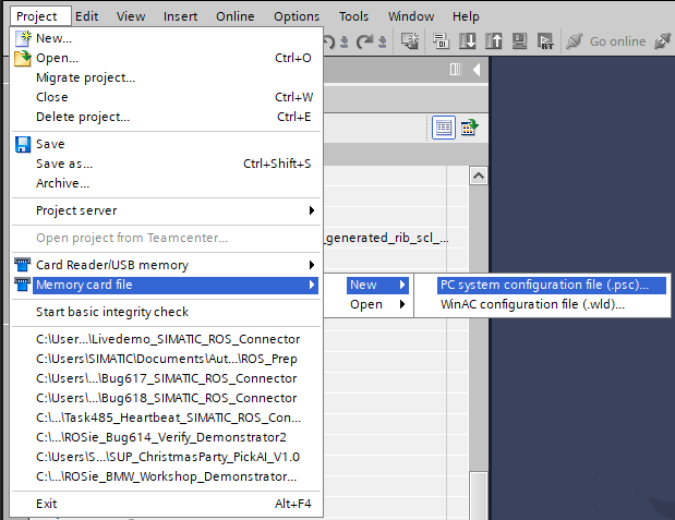
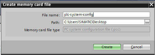
Select the name of the .psc file. Don't use whitespaces inside the filename as this file will be used in a Linux-based OS in another step of the generation process.
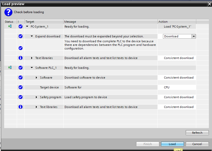
Load your OpenController or IPC device into the .psc file by dragging and dropping the device onto the created Memory Card file:
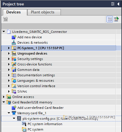
A dialog will open. Press on load to load the device configuration into the .psc file.
8. Move .psc file to ROSie input directory
Now copy the created .psc file into the input directory of your ROSie workspace. If you are using a virtual machine you can use shared folders, or if using WSL, you can directly save into your WSL filesystem (normally found under \wsl$\Ubuntu)
9. Use .psc file to continue ROSie process to generate ROS 2 package
As the .psc file is now located in the ROSie context, you can now proceed with the generation of the ros2 package. The ROSie cli tool should still be waiting for the .psc file, at the state of the end of Step3. Type in the name of the .psc file you created and press enter.
$ rosie -c config.yaml
#####################################  ROSie  #####################################
#  Version: 0.3.0                                                                 #
#  Date:    08.07.2025                                                            #
#  Time:    14:26:42                                                              #
#  Copyright (c) Siemens AG, 2025, and licensors. All rights reserved.            #
#  Portions include Open Source Software. See ReadMe_OSS_0.3.0.html for details.  #
###################################################################################

Gathering ROS 2 message types information ...
Generating PLC code ...
Please import the generated PLC code into your TIA project, export the TIA project .psc file, and place into the ROSie input folder.
Please provide the file name of the .psc in the prompt when requested, e.g., 'tia_project.psc' and press ENTER to continue the generation process or 'n' and ENTER to exit the program.
plc-system-config.psc
If the generation was successful, the output of the cli tool should look similar to this:
$ rosie -c config.yaml
#####################################  ROSie  #####################################
#  Version: 0.3.0                                                                 #
#  Date:    08.07.2025                                                            #
#  Time:    14:28:35                                                              #
#  Copyright (c) Siemens AG, 2025, and licensors. All rights reserved.            #
#  Portions include Open Source Software. See ReadMe_OSS_0.3.0.html for details.  #
###################################################################################

Gathering ROS 2 message types information ...
Generating PLC code ...
Please import the generated PLC code into your TIA project, export the TIA project .psc file, and place into the ROSie input folder.
Please provide the file name of the .psc in the prompt when requested, e.g., 'tia_project.psc' and press ENTER to continue the generation process or 'n' and ENTER to exit the program.
plc-system-config.psc
User Input: plc-system-config.psc
TIA project .psc file <plc-system-config.psc> found in input workspace. Continuing generation process ...
Generating ROSie API library and ROS 2 package ...
Successfully generated ROS 2 package and PLC code.
10. Move generated ROS 2 package to your desired workspace and build the package
Congratulations the generation process is now done. You can find the generated ROS 2 package in the output folder of your ROSie workspace under:
output/<date+timestamp>/output/ros2_deployment/ros2_ws/src/ros2_package_name
Additionally, in the same output folder you will find the configuration .yaml file that was used for the creation of the ROS 2 package, as well as logs from the creation process in case of errors.
Please be sure to exit the ROSie container before continuing the process of moving your generated package. Otherwise some problems might arise while moving files around. To exit the container simply type exit into the command line.
a. Creating a new container based ROS 2 Workspace
Within the output/ros2_deployment folder, a Dockerfile, docker compose file and build script were also automatically generated. These files can be used to build a docker image as archive which can then be loaded into your runtime system.
Navigate to the ros2_deployment folder and run the following command to build the generated ROS 2 package as a deployable image:
# build_deploy_container.sh parameters:
# ros2-version: ROS 2 version [supported: humble, jazzy, kilted], default: jazzy
# container:    Container name, default: rosie_bridge_example
bash build_deploy_container.sh --ros2-version jazzy --container rosie_bridge_example
The script will build a docker image based on the standard ROS 2 image you have selected e.g. Jazzy, then compile the ROS 2 packages and setting up the required RIB runtime dependencies for the generated ROSie node. Afterwards, the docker-compose.yaml file will be updated to use the generated ROS 2 package.
Finally, the script will export the generated docker image as a .tar archive with the name <container_name>_<ros2_version>.tar.
You can then follow these steps to deploy the generated image archive into your runtime system:
Copy the docker image archive to the Industrial OS.
scp rosie_bridge_example_jazzy.tar [USER]@[DESTINATION_HOST_IP]:rosie_bridge_example_jazzy.tar
Copy the docker-compose.yaml file to the Industrial OS.
scp docker-compose.yaml [USER]@[DESTINATION_HOST_IP]:docker-compose.yaml
Load the image again in the Industrial OS.
ssh [USER]@[DESTINATION_HOST_IP]
docker load < rosie_bridge_example_jazzy.tar
Now you are ready to run the generated ROS 2 package on your IPC via the generated docker-compose.yaml and docker compose.
b. Working on an existing ROS 2 Workspace
Although using the deploy process of docker images is recommended, you can use your existing ROS 2 workspace within Industrial OS. Therefore, all that is needed is to copy the complete ROS 2 package directory to your IPC runtime system's ROS 2 workspace and compile it via colcon build.
Running the Generated Interface
1. Start RIB_App
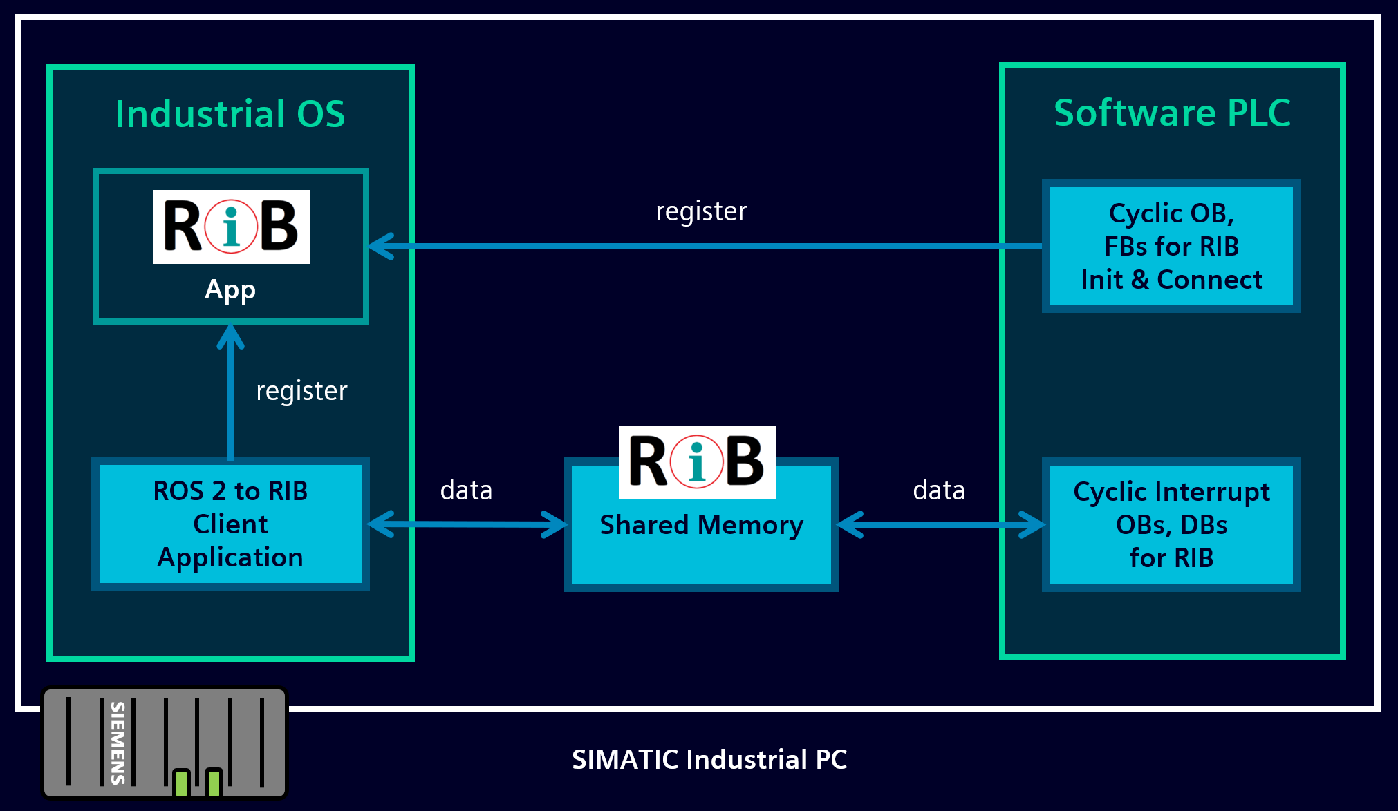
Start the RIB_App executable inside the Industrial OS of your IPC device.
RIB_App
This application serves as a RIB participant broker like shown in the following illustration:
2. Load PLC program to the Software PLC
If not done already, load the TIA project that was extended by the ROSie generated program blocks to the Software PLC.
The generated state machine will then try to automatically connect to the RIB_App.
3. Start ROS 2 Node
Start the ROS 2 node using the generated docker-compose.yaml file in your Industrial OS:
ssh [USER]@[DESTINATION_HOST_IP]
docker compose up